


IN STOCK
£249.00Add to basket
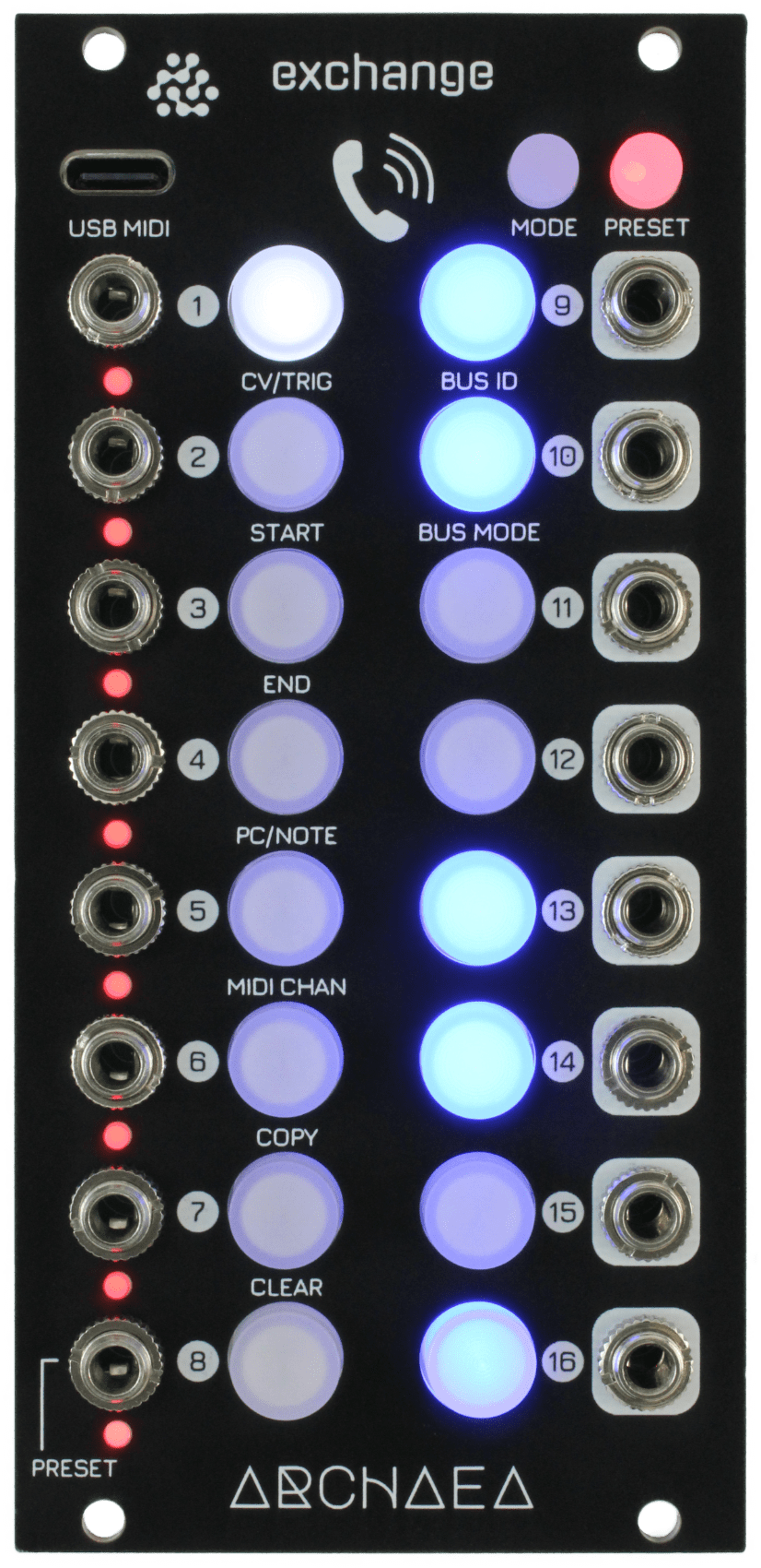
Exchange is organised into 8 inputs and outputs with buttons for each input (white) and output (blue). Exchange behaves like ‘virtual patch cords’ between the modules connected to its inputs and outputs. To connect an input to an output, the input button is first pressed, then the output button. An input can connect to more than one output, which is set by pressing more than one output button in turn.
Are inputs mixed when multiple inputs are connected to a single output?
An Exchange output can only be connected to a single input, like connecting patch cables between modules. The inputs will not be mixed into the output. Instead, each time an input is connected to the same output, the input will replace the previous input.
What about normalled inputs in my other modules?
Exchange can only patch signals available at its inputs. Other connected modules may have ‘normalled inputs’, where a signal is internally connected when an input jack is removed. If this internal signal is output by a module, it can be connected to another Exchange input (including chain inputs using the Expander or Expander 1U modules) and selected to behave the same as the disconnected input on the connected module.
Features
Specifications
Exchange has been reviewed in Sound on Sound magazine, July 2025 issue by William Stokes. Here is an excerpt from the review:
“… the linear ‘Y‑Y’ layout of the Exchange (as opposed to X‑Y) suits it perfectly to being sequenced. Simple enough to use at speed, complex enough to facilitate deep‑diving. In this way it can either be a type of ‘set and forget’ module or it can be a highly performative and dynamic one, playing a key role within a patch as well as external to it.”
The full review is available to read here.
L.A. based electronic music producer and Grammy-nominated mastering engineer Don Tyler (Remote Vision) has this to say about Exchange:
“Once you have the Archaea Exchange in your rack, you cannot imagine a world without it. The more you use it, the more ideas you have for using it. It’s also super-precise – what you put in comes out, so it’s great for V/Oct distribution across multiple destinations. It’s also got quite a few tricks up its sleeve…”
Example demos of live patching using Exchange. Sounds are produced by the Loki synth voice with external effects added. Demos have been produced by Remote Vision (Don Tyler of Synphaera).
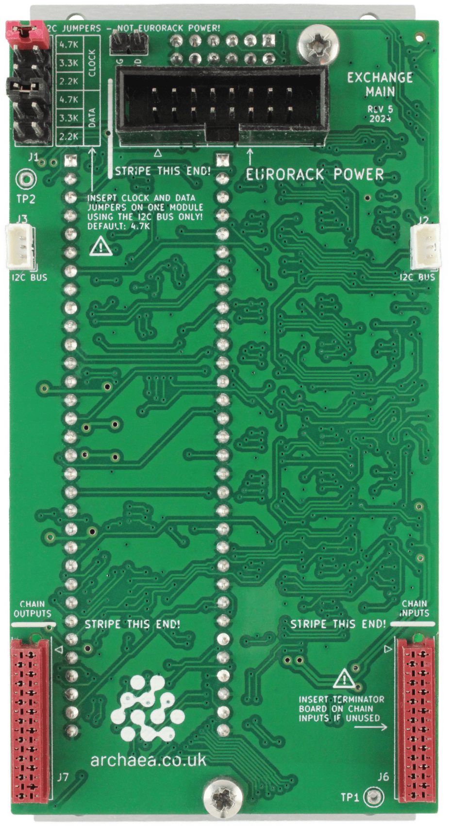
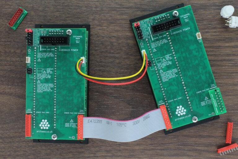
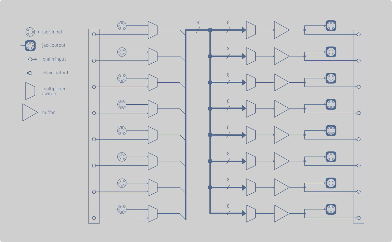
Exchange modules can be chained together using the patch chain and data bus cables. There is one patch chain input and one output connector on the rear of the module. A patch chain output on one module can be connected to any patch chain input on another module. Additionally, these patch chain inputs and outputs can be brought as jack sockets to the front panel using the Expander module. Each corresponding chain and jack input are selectable to connect to the corresponding input of the switching matrix. Each corresponding chain and jack output are both connected to the corresponding output of the switching matrix (see the block diagram below).
The data bus connectors allow Exchange modules to communicate with each other. There are two connectors on each module to allow them to be easily connected in a chain to form a set of shared communication connections known as a ‘bus’. The bus allows the modules to communicate their settings, e.g. when one module changes preset, all other connected modules can also change preset so they can form a larger patch together. Alternatively, Exchange can be configured to use the CV and gate lines of the Eurorack power header as the data bus, provided they are not being used by other modules.
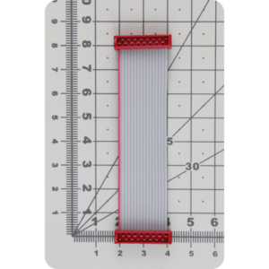
Note: Exchange is not supplied with any chaining cables, they can be purchased separately here.
| Cookie | Duration | Description |
|---|---|---|
| cookielawinfo-checbox-analytics | 11 months | This cookie is set by GDPR Cookie Consent plugin. The cookie is used to store the user consent for the cookies in the category "Analytics". |
| cookielawinfo-checbox-functional | 11 months | The cookie is set by GDPR cookie consent to record the user consent for the cookies in the category "Functional". |
| cookielawinfo-checbox-others | 11 months | This cookie is set by GDPR Cookie Consent plugin. The cookie is used to store the user consent for the cookies in the category "Other. |
| cookielawinfo-checkbox-advertisement | 1 year | The cookie is set by GDPR cookie consent to record the user consent for the cookies in the category "Advertisement". |
| cookielawinfo-checkbox-necessary | 11 months | This cookie is set by GDPR Cookie Consent plugin. The cookies is used to store the user consent for the cookies in the category "Necessary". |
| cookielawinfo-checkbox-performance | 11 months | This cookie is set by GDPR Cookie Consent plugin. The cookie is used to store the user consent for the cookies in the category "Performance". |
| viewed_cookie_policy | 11 months | The cookie is set by the GDPR Cookie Consent plugin and is used to store whether or not user has consented to the use of cookies. It does not store any personal data. |
| Cookie | Duration | Description |
|---|---|---|
| _ga | 2 years | This cookie is installed by Google Analytics. The cookie is used to calculate visitor, session, campaign data and keep track of site usage for the site's analytics report. The cookies store information anonymously and assign a randomly generated number to identify unique visitors. |
| _gat_gtag_UA_197047403_1 | 1 minute | This cookie is set by Google and is used to distinguish users. |
| _gid | 1 day | This cookie is installed by Google Analytics. The cookie is used to store information of how visitors use a website and helps in creating an analytics report of how the website is doing. The data collected including the number visitors, the source where they have come from, and the pages visted in an anonymous form. |